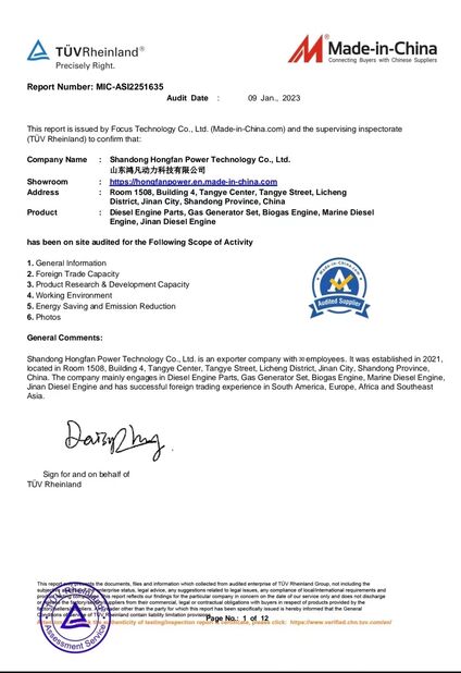
-
MichalisToday we have taken the order we made to our base and everything looks great. Thank you very much for you service ang for sure we will cooperate again within the near future.
-
Nursultan B.Working with this company has been a fantastic experience. They provide reliable products and excellent service. Their team helped us through every step, ensuring smooth installation and setup of our generator. We appreciate their professionalism and expertise!"
-
Hossein A.This company stands out for its dedication to customer satisfaction. The entire process, from consultation to delivery, was seamless. Their technical knowledge and attention to detail ensured we got exactly what we needed. Highly recommended!"
-
SomchaiOur oil and gas operations require uninterrupted power, and the jichai 500KW engine delivers every time. The emission compliance is a significant plus, and the sturdy design is well-suited for Kazakhstan's challenging terrains. Truly dependable
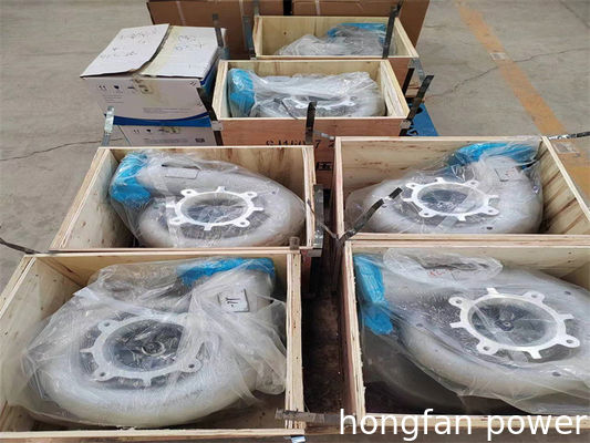
Weichai 6160 turbocharger used in marine diesel engine WHM6160 6170 6180 spare parts offer

Contact me for free samples and coupons.
WhatsApp:0086 18588475571
WeChat: 0086 18588475571
Skype: sales10@aixton.com
If you have any concern, we provide 24-hour online help.
x1. Overview of the 170Z Series Starting System
The 170Z series diesel engine supports two starting modes: electric starting and compressed air starting, designed to meet different operational needs and working environments.
2. Electric Starting System
2.1 Components
The electric starting system includes:
Battery
Starter Motor
Starting Relay
Wiring and Control Switches
2.2 Working Principle
Turn on the battery switch.
Insert and switch on the ignition key.
Press the start button.
The starter motor’s solenoid coil is energized, pushing the pinion gear to engage with the flywheel ring gear.
The starter motor rotates the flywheel, cranking the diesel engine to start.
3. Air Starting System
3.1 Components
The compressed air starting system includes:
Starting Air Bottle
Air Motor
Switch Valve
Fittings and Piping
3.2 Working Principle
Open the air valve of the air bottle.
Then open switch valve 3.
Compressed air flows through the pressure reducing valve, switch valve, and oil mist device into the air motor.
Air pressure drives the motor blades, rotating the rotor and output shaft.
The output gear engages with the diesel engine flywheel, initiating startup.
Once the engine starts, immediately close the switch valve to stop the air supply.
4. Precautions for Electric Starting
Starting time must not exceed 5 seconds; release the button immediately after the engine starts.
Wait at least 2 minutes between restart attempts if the engine fails to start.
Do not press the start button again until the flywheel and pinion have fully stopped rotating.
If the engine fails to start three times in a row, inspect and troubleshoot the system.
During maintenance, ensure waterproofing of electrical components to avoid short circuits.
The battery must supply 24V with a capacity of no less than 195Ah, and the cable cross-section must be greater than 70mm².
5. Precautions for Air Starting
Clean all pipe fittings before installation to avoid blockages or motor blade damage.
Use Loctite 567 for sealing pipe joints.
Before starting, check the oil mist device to ensure it contains proper oil (32L-DAB or N32 grade) at not less than 1/3 full.
Never start if the oil mist device is empty.
Operating pressure of the air motor should be 0.7–0.9MPa; maximum allowable pressure is 1.0MPa.
If starting fails, the gear remains engaged for a second attempt without needing to reset.
Immediately close the valve after engine start to prevent gear damage.
The air motor must not run unloaded for long durations at working pressure.
6. Use and Safety Instructions for Starting Air Bottles
6.1 Operation Procedure
Open air valve 3, then open the central large valve 1 to allow air to reach the switch valve.
Once the diesel engine is running, immediately close valves 1 and 3 to stop airflow.
6.2 Air Charging Guidelines
Inflate the bottle until pressure reaches 2.45–2.94MPa.
At 3.29MPa, the safety valve (valve 5) will release excess pressure automatically.
Minimum resealing pressure for the safety valve is 2.3MPa.
6.3 Bottle Placement and Connections
The air bottle must be stored upright.
Multiple bottles can be connected in series for larger capacity.
The inner diameter of connecting pipes must be at least Φ12mm.
The air motor line uses a G1 pipe, ideally shorter than 2m.
Pipeline pressure resistance must be ≥6MPa.
6.4 Warnings & Requirements
The safety valve (5) must not face the operator—risk of high-pressure air injury.
Valve port 4 is used for manual inflation with a hand-held compressor when no air source is available.
When opening the base valve, fully unscrew it to activate the reverse seal device, reducing leaks.
A spiral tower at the bottle’s base allows draining of condensed water and dirt.
6.5 Charging Valve Operation (See Figure 3-6-4)
Stop fuel injection by opening the bleed screw on cylinder 1.
Fully open charging valve 2 and then central large valve 1.
Open the charging handwheel and operate the charging handle (2).
Stop charging when pressure reaches 2.5MPa.
Charging is typically performed before engine shutdown.
⚠️ Do NOT use explosive charging (i.e., charging while fuel injection is active), as this can:
Cause valve failure
Burst pipes and gauges
Damage rubber seals
If possible, use an air compressor rated at 2.94MPa with 5–10m³/h output for controlled charging.
6.6 Explosion Prevention
Install a check device on the main starting air pipeline to prevent explosions caused by valve failure.
⚠️ Do not remove the check device — serious safety hazard.